
Reading this in your email? For a better view of the blog - click
here!
This week’s guest blog is from architect and historian Jane Griswold Radocchia. You can learn more about her work in her personal blog. She writes here about her encounter with one of Dan McKeen’s barn restoration projects and how she could determine that the builder of this 1791 barn used geometry to build the original frame.
“I invited myself to a Green Mountain Timber Frames barn dismantling earlier this fall. Of course I was glad I went.
Here’s what I saw:
 The three barns sat, connected in an L shape beside the road on the uphill slope of a valley. None of them faced the road, on their west and windy, side. Instead they faced south and east, creating a protected barnyard, a sun pocket. In the middle, protected from storms and wind, was the corn crib. Other farm buildings repeated the pattern, facing south, no doors on the west.

Hartford NY Corn Crib
The main barn also had a door on the north, directly across from the one facing south. It fronted on the farm road and looked at the house across the way. Two doors across from each other were for threshing and ventilation; a north-facing door was for bringing in hay and grain on the shady side of the barn in summer.

North side view of timber frame
 How could I tell that geometry was used in building this frame?
After we had climbed up to the rafters, Dan McKeen handed me prints of the frame measured and drawn up by James Platteter. James Platteter is a master furniture maker and Dan was lucky enough to work with him on this project and have him dedicate his time to drawing up the detailed plans. (Do take a look at Jim’s beautiful work on his website.)
To have a sense of the building, I checked some of the dimensions. The framer really did make his barn 30’- 1” wide! He also made it 42’-6” long. The diagonal of a 30’ x 30’ square will be 42‘-6” long. The shape of the floor for the barn is based on √2.
Both that extra inch and the √ are indications that the master-carpenter for this barn used geometry to determine its size and framing.
The carpenter had a pretty good rule! Over 30′ and his rule was only off by 1”. But how did he share his dimensions with apprentices if their rules differed from his?
He used geometry!
Geometry is a language, one most of us haven’t mastered. Our ancestors spoke (drew!) it well and used it for construction.
How did the farmer build his barn?
He probably hired a timber framer, a master builder. The framer knew about how big his barn should be and how it would be used. He began his design with a square with 30′ sides. This initial measurement of 30′ set the foundation for all the measurements of the barn.
How?
One side of the square would become the width of the barn. Then, the builder crossed the square with its diagonals – corner to corner – and swung his compass, extending the diagonal to meet the side of the square. The length of the diagonal became the length of the barn.
Above, is the floor plan of the barn: 30′ wide, 42′-6” long.
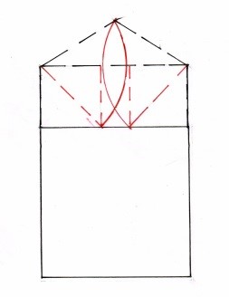
The new rectangle on the end of the square was also a good height for the wall of the barn. So the framer drew a square on each corner. Using the diagonals for those squares he swung an arc to locate the ridge. You can see the squares and the diagonal in the diagram below.
 The framer may have used the barn floor for his layout just as carpenters today use the floor of a house to lay out rafters for the roof above. If so, it would have looked like this:
 Here is the drawing of the end elevation showing that layout.
 The red x on the right is the original square. The dashed line is the arc locating the ridge. To locate the second intermediate post the framer used the side of the square, the height of his wall, as an arc.
 Where it crosses the diagonal, he placed the post.
 The north and south walls used the same geometry. The right end was laid out as was the end wall. The space for the door was a square. The left side was divided in half, as marked below by the diagonals. I enjoy finding that the braces followed the line of the diagonals. The barn door height was determined by the point where the arcs cross.
 The east wall used the same geometry – first the square at its diagonal marking the right hand intermediate post; then the remaining space divided in half.

The framer applied this same geometry as he laid out the roof, the braces and collar ties. The whole barn evolved from his first length: 30’-1”.
I look at this: so simple, so sophisticated. I am amazed! The geometry is there, but we have forgotten it. It is so beautiful!.
I will follow Green Mountain Timber Frames as they dismantle other pre-1800 barns and house frames for more confirmation of how early timber framers used geometry in structural design.”

Cristal clear analysis. I have encountered many comparable claims but few back them up with ACCURATE measurements as in this post That made a short but interesting read. Thank you for the comprehensive explanation.